
Beam soffit formwork is one of the most direct load-bearing areas in an aluminum formwork system. Beam side forms mainly control section size and line appearance, while beam soffit formwork must carry the self-weight of fresh concrete, rebar weight, construction load, and vibration disturbance. These loads are transferred through steel props, U-heads, early striking heads, and horizontal bracing to the slab or foundation below. If the beam soffit formwork and steel props do not work together properly, minor problems may include soffit deflection and slab-beam interface misalignment; serious problems may affect support-system stability and structural forming safety.
Camber control and prop removal judgement are two key steps in beam soffit aluminum formwork construction. If the camber is too small, the beam soffit may deflect. If it is too large, the soffit line may become unnatural after stripping, affecting ceiling work and finished clear height. Removing props too early forces the structure to carry load before strength, span condition, and upper construction loads meet requirements. Removing props too late affects formwork turnover and construction rhythm. CIEZN Formwork’s aluminum formwork system includes panel, support, connection, and reinforcement systems, and the support system is suitable for beams, slabs, and cantilever structures. These systems deliver their value only when design, installation, review, and stripping are controlled together.
The beam soffit formwork defines the beam soffit elevation, beam width boundary, and bottom concrete surface. The steel props transfer the load carried by the beam soffit formwork safely down to the structure below. The relationship is not simply “holding it up.” It is a load-bearing system made up of formwork, early striking heads, U-heads, vertical props, transverse bracing, bottom ledgers, and the bearing capacity of the base.
In aluminum formwork construction, beam soffit panels are usually installed together with beam side forms, slab formwork, support heads, and vertical props. Even if the beam soffit panel is positioned accurately, poor prop elevation, plumbness, or spacing can still lead to deflection, grout leakage, or local settlement after concrete placement. Conversely, even a stable support system cannot guarantee beam soffit quality if the beam soffit panel layout, joints, and camber line are wrong.
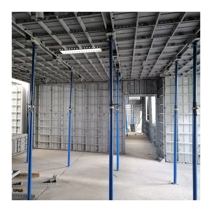
Steel prop layout below beam soffits should not be copied from experience alone. The larger the beam section, the longer the span, the thicker the slab, and the more concentrated the construction load, the higher the requirements for support capacity and stability. Ordinary residential standard-floor beams may use a relatively standardized support layout, but transfer beams, edge beams, cantilever beams, drop beams, and large-section beams should be reviewed separately.
CIEZN’s support system includes different prop types for roofs, beams, and cantilever structures, helping keep panels firmly positioned. Its steel prop product page also includes different types such as heavy duty props and push-pull props. On site, prop spacing, U-head extension, support height, longitudinal and transverse bracing, and base bearing conditions should be determined according to the project-specific method statement.
| Influencing factor | Impact on support layout | On-site control point |
|---|---|---|
| Beam depth and beam width | A larger section means higher fresh concrete self-weight. | Beam soffit prop spacing and U-head capacity need to be checked. |
| Beam span | The longer the span, the more sensitive deflection control becomes. | Camber value, support point location, and retained supports need special control. |
| Slab thickness | Slab load is transferred into the beam-slab support system. | Beam soffit supports and slab supports should be arranged as a coordinated system. |
| Construction load | Rebar stacking, pump pipes, and worker activity increase temporary loads. | Concentrated material stacking is prohibited in weak beam soffit areas. |
| Lower bearing surface | Insufficient slab strength or foundation bearing capacity can cause support settlement. | Use bearing plates and review slab strength and reshoring requirements. |
Before beam soffit formwork installation, review the floor control elevation, beam soffit elevation, slab soffit elevation, beam depth, and their relationship with the finished architectural level. Many cases of beam soffit deflection or slab-beam interface misalignment are not created during concrete placement. They are already formed early in installation, when U-head elevations are adjusted inconsistently or the beam soffit panels are not leveled against the control line.
The site should work from a unified elevation control point. Adjust the steel props and U-heads first, install the beam soffit formwork next, and finally close and correct it together with the beam side forms and slab panels. Do not wait until all beam side forms and slab panels are installed and then force the U-head upward to recover elevation. That can create local stress in the beam soffit formwork, open panel joints, and misalign adjacent slab panels.
The purpose of beam soffit camber is to offset possible deflection during construction and service, so the stripped beam soffit line stays close to the designed shape. Camber should not be applied mechanically with one value for every beam, and it should never be raised casually based on worker experience. It should be determined from the structural design notes, project-specific method statement, beam span, beam section, formwork system stiffness, and concrete age requirements.
A common site problem is a discontinuous camber line: the beam ends are normal, but the mid-span suddenly rises, or one U-head pushes the soffit into a kink. The correct approach is to use the beam-end elevation and mid-span camber value as control points, then use a string line or laser equipment to form a smooth transition. The beam soffit formwork should rise gradually, not suddenly at one support point.
| Camber control item | Correct practice | Common mistake |
|---|---|---|
| Camber basis | Determine according to design notes and the project-specific method statement. | Applying one experience-based value to all beams. |
| Control points | Review beam ends, mid-span, and areas near supports separately. | Adjusting only one U-head at mid-span. |
| Line shape | Use a string line and create a smooth transition. | Creating a kink or local high point on the beam soffit. |
| Support adjustment | Fine-adjust U-heads evenly at multiple points. | Forcing one point upward and opening panel joints. |
| Review timing | Recheck after installation, after rebar fixing, and before concrete placement. | Measuring only once during initial installation. |
The installation quality of steel props directly determines whether the beam soffit formwork can carry load steadily. Vertical props should be plumb. The base should sit on a reliable bearing surface. The U-head screw extension should remain within the range allowed by the method statement. Horizontal bracing and bottom ledgers should be installed between supports as required. For higher supports, edge beams, cantilever beams, and areas with local level differences, necessary diagonal stability measures should also be installed.
The prop base must not sit directly on loose subgrade, debris, insulation board, or a slab that has not reached the required bearing condition. If the support sits on a cast slab, judge whether reshoring is needed according to concrete strength, upper load, and the construction method statement. Beam soffit supports and slab supports should not work separately, especially around slab-beam interfaces, where the support system should form overall stability.
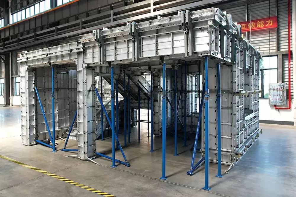
Beam soffit formwork is not an isolated forming component. It must close properly with beam side forms, slab formwork, and wall-column formwork. The joint between the beam soffit and beam side form determines whether the internal corner is clean. The joint between the top of the beam side form and the slab panel determines whether slab-beam misalignment can be controlled. If beam soffit elevation, beam side form height, and slab panel elevation are not corrected together, grout leakage at internal corners and misalignment along beam edges can easily appear after concrete placement.
During installation, confirm the beam soffit elevation and camber line first, then install beam side forms and lock the connectors, and finally close the system with slab panels. The internal corner joint at the beam soffit should be tight, with joint sealing measures used where the project requires them. The contact surface between the beam soffit formwork and early striking head or support head must be flat, without local suspension or single-point loading.
| Closing position | Control focus | Quality risk |
|---|---|---|
| Beam soffit and beam side | Tight internal corner and complete connectors. | Beam soffit grout leakage, broken edges, and unclear lines. |
| Beam side and slab panel | Consistent top elevation and straight edge line. | Misalignment at the slab-beam interface. |
| Beam soffit and support head | Stable contact and centered load transfer. | Local deflection or eccentric support loading. |
| Beam end and wall-column node | Square node and rebar not pressing against formwork. | Beam end displacement and node grout leakage. |
| Cambered mid-span | Smooth line shape and even adjustment across multiple support points. | Mid-span kink or excessive reverse camber. |
After beam soffit formwork and steel props are first installed, the area usually goes through rebar fixing, MEP embed work, worker traffic, and temporary material stacking. By the time concrete placement starts, the support-system condition may have changed. Before concrete placement, the beam soffit elevation, camber line, prop plumbness, U-head tightening, base bearing condition, and slab-beam interface must be checked again.
The area below the beam soffit should be kept clean so formwork watchers can see the support condition. High beams, deep beams, transfer beams, long-span beams, and cantilever beams should be listed as key watch areas. During concrete placement, if any loose support, slipping U-head, grout leakage at beam soffit joints, or base settlement is found, stop the local placement immediately and deal with it.
Aluminum formwork systems often emphasize fast turnover, but fast turnover does not mean all supports are removed at the same time. In beam soffit areas, distinguish between removing beam side forms, removing beam soffit panels, stripping early-turnover panels, and removing retained supports. Some systems allow part of the beam-slab panels to be removed while retained supports remain untouched, improving turnover efficiency. But load-bearing supports must stay in place according to concrete strength, span, and method statement requirements.
CIEZN aluminum formwork has the construction advantage of removing slab panels without moving the supports. For beam soffit formwork, this should be understood as separate management of “panel turnover” and “structural load bearing.” Before support removal conditions are met, U-heads must not be loosened and reshoring supports must not be moved just to speed up the schedule.
| Removal object | Can it be removed early? | Key judgement point |
|---|---|---|
| Beam side formwork | Usually removed earlier | Only when the concrete surface and edges will not be damaged. |
| Beam soffit panels | Depends on the system and method statement | Removal must not affect retained supports or beam soffit load bearing. |
| Panels around early striking heads | Follow the aluminum formwork system requirements | Retained support heads and vertical props must not move. |
| Beam soffit load-bearing supports | Must not be removed casually early | Judge by strength, span, upper load, and method statement. |
| Reshoring supports | Retain according to construction-stage load | Do not remove before upper construction loads are clarified. |
Beam soffit prop removal should not be judged by whether the concrete “looks hard.” It should consider the concrete strength report, same-condition curing test blocks, structural span, beam section, design requirements, project-specific method statement, upper construction load, reshoring system, and weather curing conditions. For long-span beams, heavy-load beams, or beams that will continue to carry upper construction work, prop removal conditions should be handled more conservatively.
Site management should usually follow a written approval process: the crew submits a prop removal request, the technical lead checks strength and method statement requirements, quality and safety staff inspect the support condition on site, and removal starts only after everything is confirmed. Prop removal should be carried out by zones and sections in sequence. Large-area simultaneous loosening of U-heads or removing key load-bearing supports first is strictly prohibited.
| Quality or safety problem | Possible cause | Improvement measure |
|---|---|---|
| Beam soffit deflection | Insufficient camber, prop spacing too wide, U-head slipping, or support settlement. | Review camber value and support layout; check U-heads and base bearing before concrete placement. |
| Excessive reverse camber | Camber value increased casually or mid-span jacked at one point. | Control according to design and method statement, adjust evenly at multiple points, and recheck with a string line. |
| Slab-beam interface misalignment | Beam soffit, beam side, and slab panel elevations not corrected together. | Remeasure beam soffit and slab soffit elevation together before closing. |
| Beam soffit grout leakage | Loose joint between beam soffit and side form, or support deformation opening the joint. | Repair formwork edge ribs, complete connectors, and check support stability. |
| Cracks or deformation after prop removal | Insufficient concrete strength, upper loads not reviewed, or retained supports removed early. | Follow prop removal approval and judge by strength, span, and construction load. |
| Slow formwork turnover | Boundary between early striking and retained supports is unclear, and stripping sequence is disorganized. | Clarify panel removal, support retention, and reshoring management procedures. |
Not every beam uses the same camber method. Whether camber is needed and how much should be determined by structural design notes, the project-specific method statement, beam span, and formwork system stiffness. It should not be raised casually based on experience.
It can be adjusted according to the method statement after confirmation by the technical lead, but the crew must not widen spacing or reduce supports casually. If beam depth, span, load, or lower bearing conditions change, the layout should be reviewed again.
No. Early striking usually means removing some panels or non-load-bearing formwork while key supports remain in place. Beam soffit load-bearing supports can be removed only after concrete strength, span, and construction load conditions are satisfied.
Strength and method statement requirements should be the core basis. Age is only a reference. On site, judge together with same-condition curing test blocks, design requirements, span, upper loads, and the reshoring system.
Common causes include insufficient camber, support settlement, premature prop removal, excessive upper load, or inadequate reshoring. Trace back through support layout, strength evidence, prop removal approval, and construction load management.
The key to coordinating beam soffit formwork and steel props is to manage elevation, camber, load bearing, stability, and prop removal conditions as one system. Beam soffit formwork is responsible for forming; steel props are responsible for load transfer; camber control manages line shape; and prop removal judgement protects structural safety and turnover rhythm. If any one step is simplified, beam soffit deflection, misalignment, grout leakage, or prop removal risk can follow.
For main contractors, aluminum formwork subcontractors, and procurement teams, aluminum formwork system selection should pay attention to the supplier’s support-system configuration, beam soffit early striking nodes, detailed panel layout, and on-site technical briefing ability. Only when beam soffit formwork and steel props are treated as a complete construction system can the fast turnover, high accuracy, and reduced repair advantages of aluminum formwork really show on site.
Phone: +8618711321769
Email: alame.vicky@gmail.com
WhatsApp: +8615400055585
Address:No.88, Shuntian Avenue, Xiangyin District, Xiangjiang New District Hunan Province

 EN
EN
 RU
RU
 AR
AR
 ES
ES