
Door and window openings are among the areas where small dimensional errors in aluminum formwork are most likely to be magnified by later trades. Once the main wall surface has been cast, any error in opening width or height, verticality, diagonals, frame-edge straightness or rebate position can affect window and door frame installation, waterproof perimeter sealing, plaster repairs, facade lines and interior finishes.
Accurate opening formwork is not simply a matter of placing a box inside the wall panels. It requires a closed control loop covering formwork detailing, door and window schedule checks, setting out, frame-panel assembly, pin-and-wedge connections, waler reinforcement, concrete placement and protection during striking. The CIEZN Formwork aluminum formwork system is customized to project drawings, allowing door and window openings to be cast together with walls, slabs, beams, columns, stairs and balconies. The more integrated the system, the more important it is to define opening dimensions and reinforcement details before work begins.
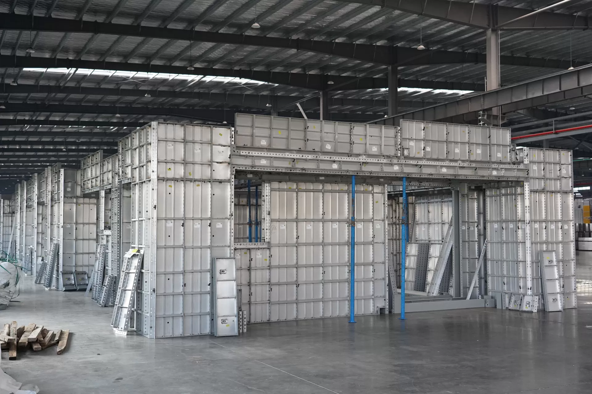
A door or window opening may look like a simple void in a wall, but it involves the architectural drawings, structural drawings, door and window schedules, external insulation, plaster thickness, sill coping, lintels, boundary columns, rebates, waterproofing details and frame-installation clearances. If any one of these inputs is not checked, the formed opening may not meet the needs of the following installation work.
Aluminum formwork is stiff and can be reused many times. It produces crisp lines and stable dimensions, but an incorrect detailed dimension or inadequate site reinforcement can also reproduce the same error across many typical floors. Opening quality control should therefore be established on the first or benchmark floor, not postponed until the window and door contractor arrives and extensive repairs become necessary.
The first step is to distinguish the opening formed during structural work from the clear opening required for installation of the finished frame. The structural opening normally needs to allow for later plaster, insulation, waterproof mortar, the perimeter installation gap, packing or sealing material, and the finish build-up. If the formwork is sized only to the outside dimensions of the manufactured frame, there is often too little room for installation.
Before detailing the aluminum formwork, compare the architectural door and window schedule, elevations, floor plans, wall sections, structural wall thicknesses and the clearances required by the door and window supplier. External windows, entrance doors, equipment-platform doors, service-shaft access doors and stairwell windows are particularly likely to have non-standard dimensions because of changes in elevation, wall thickness or facade profiles.
| Item to verify | Key information | Control purpose |
|---|---|---|
| Architectural door and window schedule | Opening reference, width and height, opening direction and sill height | Confirm opening type and the source of its dimensions. |
| Structural drawings | Shear-wall thickness, coupling beams, concealed columns, lintels and reserved opening locations | Prevent clashes between opening formwork, reinforcement and boundary elements. |
| Elevations and detail drawings | Facade profiles, rebates, insulation, drips and sill coping | Ensure the formed frame meets facade and waterproofing requirements. |
| Finishing details | Plaster thickness, tiles, stone and door-lining substrate | Allow sufficient installation clearance and reduce later cutting. |
| Door and window contractor requirements | Overall frame dimensions, perimeter gap and fixing-bracket locations | Coordinate the structural opening with the installation sequence. |
Opening formwork must not be treated as an isolated component. It has to be laid out together with standard and special-size wall panels, internal and external corner panels, K panels, walers, flat ties or through-tie systems, and wall stop-end panels. The areas around openings concentrate changes in wall-panel loading and joint patterns, so the detailed design should avoid excessive small infill panels, misaligned holes and missing reinforcement points.
Before installing opening panels, verify the wall grid line, wall face lines, opening edge lines, sill elevation, door-head elevation and floor control level. Width and height are not the only considerations; position matters just as much. If windows on successive floors shift sideways, the facade will look uneven even when each individual opening is within its dimensional tolerance.
A practical method is to check the centerline, edge lines and elevation together. First confirm the relationship between the opening centerline and the grid or wall face. Then verify the distance to each jamb line, followed by the top and bottom elevations. For external windows, spot-check a vertical line through multiple floors to confirm that openings align on the facade.
| Control line | Checking method | Likely problem if incorrect |
|---|---|---|
| Opening centerline | Check against grid lines, wall faces and facade setting-out lines | Windows do not align vertically and the facade appears uneven. |
| Opening edge lines | Measure the position of the left and right jamb panels | Opening is too wide or too narrow, making frame installation difficult. |
| Sill elevation | Transfer from a common floor datum | Sill heights vary and horizontal facade lines do not align. |
| Door-head line | Check against the schedule and finished-floor level | Insufficient door-head height restricts lining or leaf installation. |
| Wall vertical-control line | Check together with push-pull prop adjustment | Poor jamb verticality and excessive diagonal difference. |
The formed quality of an opening frame depends mainly on four areas: the two vertical jambs, the lintel soffit at the head, the sill or threshold at the bottom, and the four corners. The jambs determine verticality and width; the head controls opening height and level; the bottom affects sill elevation and drainage falls; and the corners define the appearance of the stripped concrete lines.
During assembly, jamb panels must fit tightly against the wall panels, corner panels must be square, and rebate formers must be positioned accurately. Door and window rebates, grooves, drip channels and external waterproofing details should be formed in the initial pour wherever possible instead of being cut later. All joints must fit closely. Joint-sealing strips or foam strips may be used where required by the project to prevent grout loss at corners.
Openings create numerous edges and complex boundaries, so local stiffness is often lower than it is in an uninterrupted wall panel run. During casting, fresh-concrete pressure and vibration can make the frame bulge, twist or develop offsets. Missing pins and wedges, incomplete walers or an open tie arrangement can leave the stripped opening with variable width, bowed edges and visible joints in the surrounding wall.
CIEZN aluminum formwork accessories include wedge pins used to secure panels in conjunction with tie systems. Around openings, these connectors are not optional small hardware. They must be installed in full accordance with the detailed drawings and approved method statement. At concentrated load points, walers, hollow sections, push-pull props or temporary supports should be added to improve overall stability.
| Reinforcement location | Main control | Quality risk |
|---|---|---|
| Vertical jambs | Continuous walers, complete connectors and straight edge lines | Jambs bulge and the clear opening width changes. |
| Lintel soffit at the head | Level, support stiffness and complete corner closure | Insufficient opening height or an offset at the head. |
| Sill or bottom edge | Elevation, fall and support stability | Uneven sill and difficult waterproof perimeter sealing. |
| Four corners | Square corner panels, tight joints and fully locked wedges | Grout loss, broken corners and poorly defined internal or external arrises. |
| Wall panels around the opening | Wall walers coordinated with local opening reinforcement | Wall flatness passes inspection while the opening deforms locally. |
The areas around door and window openings commonly contain concealed columns, coupling beams, lintels, local reinforcement, wall ties, embedded railing or protection fittings, and sometimes embedded door or window fixing points. When reinforcement clashes with opening panels, crews may force or pry the formwork into place or omit local connectors, directly compromising the opening dimensions.
Before closing the formwork, check concrete cover at the opening edges, embedded-item positions and plumbing or electrical sleeves. Reinforcement must not bear directly against aluminum panels, and cover spacers must be stable. Embedded items must not occupy corner-panel locations, rebate formers or connection holes. Where frame fixing points require embedment, coordinate them in advance with the door and window contractor and structural designer.
Concrete placement can still change frame dimensions after the opening formwork has been installed. This is particularly true for tall windows, door openings, the underside of coupling beams and walls with closely spaced openings. Concentrated discharge on one side or prolonged vibration creates uneven lateral pressure and can move the jamb panels.
Control lift thickness and placement rate so the concrete rises as evenly as possible on both sides of an opening. Do not hold the poker vibrator against opening panels, corner panels or rebate formers. The formwork watch should focus on all four corners, the lintel soffit, jamb joints and waler connections. Grout leaks, loose fittings and movement must be corrected promptly.
Measure the opening promptly after stripping. Width and height alone are not enough; also check jamb verticality, head level, sill elevation, diagonal difference, edge straightness and corner finish. If systematic errors appear on the benchmark floor, trace them back to the detailed drawings, panel numbering, setting out and reinforcement measures, then correct them on later floors.
Do not pry corner panels or rebate formers aggressively during stripping. External corners, sill edges and the bottom of door openings are prone to spalling, so follow the specified concrete-strength requirement and stripping sequence. Clean removed panels promptly and inspect the edge ribs, holes, welds and corners for deformation before the next cycle.
| Inspection item | What to check | Corrective direction |
|---|---|---|
| Opening width and height | Compare with detailed dimensions and required installation clearances | Determine whether panel arrangement or setting-out lines require adjustment. |
| Verticality | Confirm that both jambs are straight and plumb | Check wall-form alignment, walers and push-pull props. |
| Diagonals | Confirm that the opening is square | Investigate corner panels, frame panels and connectors. |
| Elevation | Check sill, door head and lintel soffit for consistency | Review floor-level transfer and bottom support. |
| Finish | Inspect internal and external arrises, grout loss, honeycombing and spalling | Improve joint fit, sealing, vibration and protection during stripping. |
| Problem | Common cause | Control measure |
|---|---|---|
| Opening too small | Installation gap and finishes omitted, or panels set inward | Coordinate structural and installation openings during detailing and recheck edge lines on site. |
| Opening too large | Frame panels move outward, connectors are missing or lateral pressure is excessive | Install all pins and wedges, strengthen walers and ties, and control placement rate. |
| Frame edges out of plumb | Wall formwork is inadequately aligned or jamb panels are not fixed securely | Align jamb panels together with the wall formwork and add push-pull props or temporary restraints. |
| Excessive diagonal difference | Corners are not square or left and right jambs are positioned inconsistently | Trial-assemble corner panels and recheck centerline and edge lines during setting out. |
| Grout leakage at corners | Loose joints, deformed corner panels or inadequate sealing | Repair or replace corner panels and install the specified joint-sealing measures. |
| Inconsistent sill elevation | Incorrect level transfer or inadequate support beneath the sill panel | Use a common level datum and remeasure after installation and before casting. |
The key points are the source of the dimensions, site setting out and reinforcement of the opening frame. Structural and installation openings must be distinguished, edge lines and elevations must be checked together, and connectors, walers and ties must give the frame sufficient stiffness.
The verticality, diagonals, wall thickness, rebate position or allowance for finished surfaces may be inaccurate. Installation requires more than width and height; the opening must also be square, straight and large enough for the specified perimeter gap.
Check corner panels for deformation, make sure joints fit tightly, and install every pin and wedge. Use the project-specified sealing material where necessary, and do not let the vibrator strike corner formwork continuously during placement.
Yes. A benchmark floor can verify the schedule, detailed dimensions, rebate arrangement, sill elevation, facade alignment and reinforcement performance before the same details are repeated across typical floors.
The supplier should provide opening details, panel layouts and numbering, trial assembly, reinforcement recommendations and a first-floor installation briefing. The project team must provide complete drawings and frame-installation requirements so both parties can reduce later cutting and repair work.
Accurate aluminum formwork around openings depends equally on early dimensional coordination and site process control. During detailing, the door and window schedule, structural opening, finishes and installation clearance must be reconciled. During installation, edge lines, elevations, verticality, diagonals and the reinforcement system must each be closed out. During casting and stripping, the panels must also be protected against movement, grout loss and damaged arrises.
When door and window openings are cast as part of a complete aluminum formwork panel system, the project can reduce later hacking and plaster repair, speed up frame installation, and achieve more consistent facade lines and interior finishes. Main contractors, formwork subcontractors and procurement teams should therefore assess a supplier's detailing capability, junction experience and site technical support, not just the panel price. Project requirements can be discussed through the CIEZN contact page.
Phone: +8618711321769
Email: alame.vicky@gmail.com
WhatsApp: +8615400055585
Address:No.88, Shuntian Avenue, Xiangyin District, Xiangjiang New District Hunan Province

 EN
EN
 RU
RU
 AR
AR
 ES
ES